LED signalling
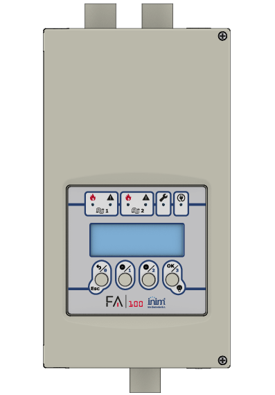
FA100 provides signals via the LEDs on the user interface, located above the LCD display on the lid (Description of parts, [E]), referring to the entire system or to the single aspirator and detection line ( and
and  ).
).
Further information is provided by the LEDs that motherboard is equipped with (Description of the PCB, [J]).
Frontal LEDs
|
LEDs |
signalling |
||
|---|---|---|---|
|
icon |
colour |
ON solid |
blinking |
|
|
green |
The device is functioning. |
- |
|
|
yellow |
The primary power supply or the auxiliary power supply (if enabled by programming) are lower than the minimum nominal value. |
- |
|
|
yellow |
The LED signals faults relating to the entire device:
|
- |
|
|
green |
Indicates that the detector module to which the icon refers is enabled and operating properly. |
- |
|
|
yellow |
Indicates a fault with the relevant detector module or related pipe:
|
- |
|
|
red |
Indicates that the level of smoke detected by the module to which the icon refers exceeds the alarm threshold. |
Indicates that the smoke level detected by the smoke module exceeds the warning threshold. |


LEDs on the motherboard
|
LEDs |
signalling |
||
|---|---|---|---|
|
label |
colour |
ON solid |
blinking |
|
RUN |
green |
The RUN/SERVICE switch is in the “RUN” position: the device is operating. |
- |
|
SERVICE |
yellow |
The RUN/SERVICE switch is in the “SERVICE” position: the device is in maintenance mode. |
- |
|
LOOP |
yellow |
If the “Automatic LED management” option is enabled on the control panel and one of the following faults is present:
|
- |
|
LOOP |
green |
The fire control panel switches on the LED |
Fast blinking (700 ms) with insufficient loop voltage (below 12.5V) Single blinking on each query received from the control panel |